Join us in asking and exploring answers to the age-old question, “Why does it work?”
As a physics major or minor, you’ll find that you’re able to contribute to our research programs right from the beginning. Even before you enroll as a physics student, there are opportunities for you to start taking part in our research programs. Once you’re a student in our courses, we listen to what you want to learn, designing our elective options based on your interests.
Explore how the world works
Physics is an investigative science testing theory against experimental measurements.
Discover something new
Learning through experimenting and collaborative research is a hallmark of our department — and of Hope College. It’s important for our students to learn directly alongside faculty members as research apprentices. Not only will you be learning something new, but you’ll be contributing directly to the field. View our blog for more information about our research groups.
Learn from the best
Each faculty member's research program is supported by external grants they've earned through competative programs. We currently have active awards totalling over $1 million. External funding has come from several nationally prestigious agencies and endowments, including:
- The National Science Foundation
- Research Corporation for Science Advancement
- The Howard Hughes Medical Institute
- NASA
- The Pew Foundation
- U.S. Department of Energy
- The Hope College endowment
For detailed information, view our faculty pages.
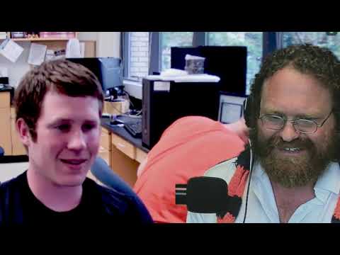
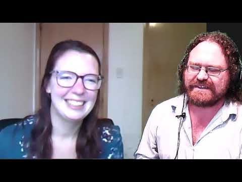
Hear from our Physics community
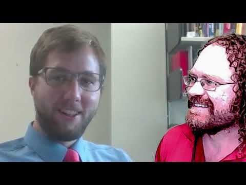
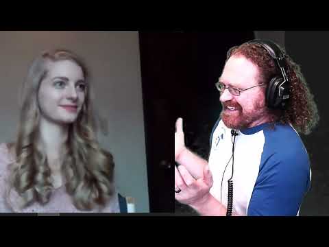
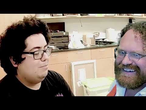
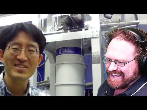
Recent blog posts
-
Physics Seminar by Luke Pinkerton (Hope‘97), Thursday (4/18) at 11 am – VDW104
Posted by cho“Direct Tension Testing” by Luke Pinkerton ’97, CEO Helix Steel Bio: Luke Pinkerton ‘97, ...
Read More -
Congratulations to Andrew Bunnell for 10 years of service at Hope Physics Department
Posted by choThe post
Read More -
Physics student presentations #3 (summer research in 2023), Thursday (4/4) at 11 am – VDW104
Posted by cho1. “Analyzing Promethium Isotopes To Understand The Origin Of Heavy Elements In The Univers...
Read More -
Physics Seminar by Dr. Kyuil Cho, Thursday (3/28) at 11 am – VDW104
Posted by choTitle: Room temperature superconductor! Is it possible?Abstract: Superconductor is a material tha...
Read More -
Physics student presentations #2 (summer research in 2023), Thursday (3/21) at 11 am – VDW104
Posted by cho1. “Turbulence and Zonal-Flow Impact in the Madison Symmetric Torus in Quasi-Single Helicity”...
Read More -
Physics student presentations #1 (summer research in 2023), Thursday (3/7) at 11 am – VDW104
Posted by cho1. “Efficient Techniques for Calculating the Energy Widths of Cyclotron Resonance in Strong Mag...
Read More
We have a proven formula for success
This formula combines rigorous classroom work and true hands-on research. It combines caring, available instructors with experienced research mentors.
VanderWerf Hall27 Graves PlaceRoom 204Holland, MI 49423
workP. 616.395.7510
physics@hope.eduHope by the Numbers
- 1.7 millionVolts
Our laboratory houses the 1.7 million volt Van de Graaf particle accelerator.
Learn more - 80%Graduate School
Our department sends students to graduate school in physics, materials science, medical physics and medicine. Those who don’t pursue further education often succeed in careers in national and industrial labs, business and secondary education.
- $1 millionRecent Grants
Our faculty has received over $1 million in recent grants toward their research.
Find research opportunities - $70kMedian Salary
The median salary for physicists with bachelor’s degrees is $70,000, and can increase by 41% for physicists with graduate degrees.
Imagine life after Hope